Drafting standards still matter
To create a drawing, you no longer have to spend hours at a drafting table with your drawing pencils, triangles, scales, French curves, compasses, dividers and erasers. Although those tools have gone by the wayside, the techniques that guided manual drawings should not.
Regardless of your engineering discipline – mechanical, architectural, welding, molding, casting, structural, civil – drawings have a common purpose: to convey information on how a part, structure or assembly is to be produced. In order to enable production, you must have clear, precise drawings that are easy to interpret. In layman’s terms, drafting standards still matter.
Modern design solutions have an arsenal of tools to create incredible drawings – automatic view creation, auto-dimensioning, parts-lists templates, title-block templates, section view commands, auxiliary-view commands, tolerance analysis and more. But the ease-of-use of these tools can cause the user to underestimate the technical knowledge needed to use them properly.
Regardless of the software or technology used, even seemingly minor errors – an arrow pointing in the wrong direction or a misplaced view – can cause major issues in manufacturability. Detailed, accurate drawings are less likely to be misinterpreted, which means it is less likely they will cause the costly re-manufacture of parts.
In this paper, we’ll discuss basic drafting techniques to help you improve the manufacturability of your drawings, including:
Focusing on clarity, precision and accuracy
Spending time on your templates
Creating personalized tables and callouts
Creating models with drawings in mind

Focus on Clarity, Precision and Accuracy
Use only necessary views and lines
One of the perennial drawing-related debates is how many views it takes to fully define a part. The answer is simple: as many as it takes. To ensure that your drawing is easily interpreted, at least two views are generally necessary, but there is no maximum. Don’t create superfluous views of every side of the part – consider what’s really needed. If the view doesn’t require dimensions, you probably don’t need it.
Also, don’t be afraid to use two sheets if you have to; don’t crowd views. Space and scale views for a uniform look and feel, leaving room for dimensioning and notes.
Consider whether you really need hidden lines, or if a section view could be used instead. Sometimes too many lines on a drawing can hinder the interpretation of it.
For assemblies, make sure the angles of your hatching lines (in sections) alternate correctly. Also check to make sure that you have proper line thickness for each type of line, whether visible, hidden, center, etc.
Put your views in the correct spot and adhere to the correct projection standard for your location. For the ISO standard, this means that your right view is to the left of your front view, your top view is below your front view (first angle projection). For the ASME standard, the opposite of this layout is used (third angle projection).
Finally, ask yourself if a colored view would be more helpful than an uncolored view. Colored views can be particularly useful in assemblies.
Use proper dimensioning techniques
Dimensions indicate the size and position of each aspect of your model, and are used to define the size, location, orientation, form or other geometric characteristics of a part. When creating dimensions, follow these best practices:
Don’t repeat dimensions across views
Don’t cross dimension lines with other dimensions
Don’t dimension to hidden features
Dimension all features in size and location
Try to use the same reference sides or points; don’t dimension from all the different edges of a part.
Spend Time on Your Templates
Begin with a good template
A well-built house must have a strong foundation. The same holds true for drawings and templates. Templates serve as the foundation for creating drawings quickly and accurately. Once your drafting techniques are solidified, creating proper title blocks is the next step for precise drawings. Title blocks will contain all of the necessary information that pertain to the part to be produced: title, part number, material, weight, scale, where it’s used elsewhere, etc. Spend time creating good templates at the beginning:
Learn the standards
Find out what others have done
Think about the order and steps for manufacture
Best-in-class computer-aided design (CAD) systems such as Solid Edge® software generally include standard templates, but these should be edited and personalized to meet your company’s needs.
First, add your company logo. This one step will make all the difference in making the template look more professional and personalized. Also, putting your company’s contact information beside or under your logo adds a nice touch.
In Solid Edge, you can also modify the lines and blocks of the standard CAD template like any other drawing so you can change the template to your liking since they are on a background sheet. If you have already created a template in another CAD package, you can export your title block as a DXF/DWG and import it. Place whatever text and symbols that you may need onto the title block.

Make use of property text
Property text is a powerful tool in the drawing world. Properly using property text can speed up your drawings by at least 25 percent. Property text is associative to characteristics in the current file, as well as to features in models attached to the current file. Property text strings can be used to retrieve file or model-related data. It is linked to that part or assembly and stays up-to-date. The text is usually entered once and does not have to be manually entered again at the drawing level if the property text is used.
In Solid Edge, property text uses the callout command tool. For example, instead of manually entering the file name every time a drawing is created, simply using the “filename-no extension” on your template will automatically populate the title block with the file name of the part or assembly when the file is saved.
To speed things up even further, you can use property text from the model. Then, as soon as that part/assembly is referenced in a draft file, those fields are populated. Items such as title or drawing number are ideal properties to link to on a draft. Try to make use of property text anywhere you can via callouts, balloons, parts lists, etc. This facilitates accuracy and eliminates redundancy in text errors on drawings.
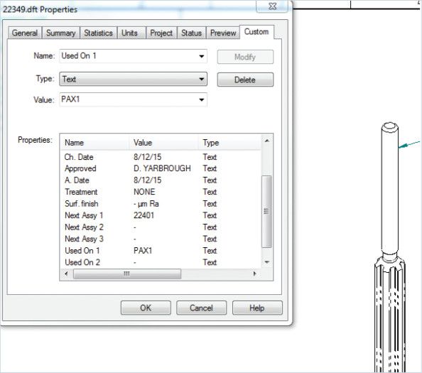 Example of custom property text being referenced in a draft file.
Set up your style
Much like the title blocks need to be tailored to meet your company’s needs, the style of the drawings will need to be updated. Items such as font, drawing view settings, line types/ thicknesses, dimension style, table formats and default hatch patterns are just a few of the parameters that can be finetuned to match your company’s style. These will need to be set in the templates as well to make sure that settings are saved and you are not setting these each time you start a new drawing. These settings are where most of your company’s drafting standards will be encompassed.
Consider template and file management
Templates are used to deal with more than just the draft files – having properties and settings set in the part and assembly files will drastically speed up drawing creation. In addition, create a central location where all of your users can find the files. If your company uses a server that all CAD users have access to, you can create a folder there for all templates and setting files. With a central location defined, simply directing all user’s computers to use those templates by default can be found in the Options > File Locations tab. If those templates are ever revised, you can update them centrally without having to go to each user’s computer to copy the templates.
Create Personalized Tables and Callouts
Save table styles for easy re-use
If templates are the foundation of efficient drawings, then saving personalized tables and callouts are the walls. While style settings cover most of the settings as far as looks are concerned on a template, they do not really cover content. Consider, for example, if your company needs parts list to have a title, and include a column for each of the following items:
Item number
Part number
Description
Quantity
Cut length
Saving this style of parts list as a personalized table allows you to easily re-use it in future drawings. You can go further by setting up the table to use certain table styles set up earlier when you created your template.
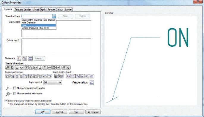
Customize callouts to company guidelines
Callouts can also be customized to meet specific company guidelines. Often, companies want callouts for items such as holes to be listed a certain way (for example, tap drill size and depth on the first line, then thread size on the second line and countersink information on the last line).
By setting up these callouts in the template, you can ensure that your drawings look consistent and uniform. The following configurable items can have saved settings:
Hole tables
Parts lists
General tables
Family of parts table
Hole/feature callouts
Note
Model with Drawings in Mind
Drawings communicate design to manufacturing
When modeling, always try to keep in mind that you will be creating a drawing of the part at hand. You will need to convey manufacturing information for the part to be procured to someone who will need relevant information on that part. Some questions to ask yourself when modeling with drawings in mind:
Have I modeled that part in a way that is easy for view generation
How is the part being used
Have I modeled that part in a way that it can be manufactured
Have I filled out all of the property text so that my drawing will automatically generate fields such as part number, material, title and tables
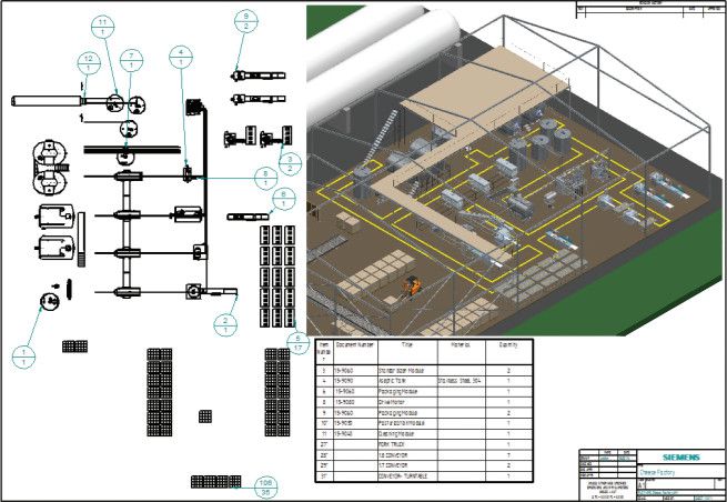
For an assembly, have I created an easy-to-follow exploded view
Have I assigned a material with proper characteristics for true mass calculations and hatching patterns
For nonsymmetrical or oddly shaped parts, have I saved additional views that I can pull from in the drawing environment to create the best visualization of the part
Have I used dimensions or notes in the model that can be pulled into the drawing automatically to reduce time spent annotating the drawing
Model each part in a way that allows for it to be easily placed and mated in any assembly that will also be used in a drawing. Be mindful to use industry-specific standards that apply to the manufacturing process of the part (such as using a draft for injection molded parts or cast parts). If you were the manufacturer, could you make it? If you address these questions during design, you will find that creating drawings becomes a painless process.
 Drawings are the final deliverable for many engineering processes – they represent a contract between design and manufacturing.
Conclusion
Proper planning makes drawing creation easy
When creating drawings, you’re only as quick as your templates allow you to be, and only as precise as your drafting training enables you to be. If you put a little bit of thought and effort into creating proper templates and learning drafting techniques, you will find creating drawings to be an efficient and effortless process. Remember:
Use only necessary views and lines, and use proper dimensioning techniques: Use as few or as many views as you need – and use extra sheets to avoid crowding views. Space and scale views for a uniform look and feel, leaving room for dimensioning and notes. Reduce the number of lines on your drawing if they make interpretation difficult. Put your views in the correct spot and use colored views where needed. Follow dimensioning best practices.
Begin with a good template, including property text and style: Templates are the foundation for creating drawings quickly and accurately. Create proper title blocks, add your company logo and include your company’s contact information. Make use of property text to automatically pull associative properties in the current file or the attached models. Define a style that matches your company’s style guide. Determine where your templates will be stored, and how others will access them.
Save table styles for easy re-use, and customize callouts: Save specific table styles for easy re-use and customize callouts to meet any required company guidelines.
Model with drawings in mind: When you are modeling, keep in mind that drawings created from your model represent a contract between design and manufacturing. Use industry-specific standards that apply to the manufacturing process of the part. If you were the manufacturer, could you make it?
Practicing these techniques and keeping the end goal of the drawing in mind will help you create production-ready drawings that eliminate confusion and avoid costly errors.
Solid Edge for CAD drawing and drafting
Good techniques are a key factor in creating production-ready drawings and your supporting CAD tool can either help or hinder your efforts. With Solid Edge, drawing layout, detailing, annotation and dimensioning controls can be used to automatically comply with the mechanical drafting standard you select. Solid Edge enables you to automatically create and update drawings from 3D models, quickly creating standard and derived views, including auxiliary, section, detailed, broken and isometric views. Solid Edge also enables you to automate the creation of exploded views, balloons, parts lists and bills-of-material (BOM) for models of any size. You can choose from a number of different display options, such as shaded, to ensure your documents communicate their intent as clearly as possible. As changes are made to the 3D model, a graphical indication alerts designers when drawing views are out of date, while a build-in tool alerts the user to what changes were made. When drawings are saved, title blocks are automatically populated using data from the part file.
Comprehensive dimensioning and annotating tools in Solid Edge enable you to create fully detailed drawings remarkably fast. Quick Sheet templates can be used to automatically populate a drawing with predefined standards, such as views, parts lists and annotations. Detailing drawing views can be automated by retrieving part or assembly dimensions; a full complement of dimensions and annotation commands are also available.