When you design sheet metal parts, you face a series of unique challenges. Although parts are typically designed in their formed state, they begin as a flat plate or sheet. As a result, manufacturability becomes a critical aspect of every feature making up the finished part. Add to this the need to account for material thickness, along with bend and corner relief, miter deformation features and critical dimensions (inside or outside), and it’s easy to see where challenges can arise. This brochure describes several techniques to help you increase productivity in sheet metal and get your designs done accurately, quickly and easily.
Tip 1: Assign a material type and thickness before starting your design
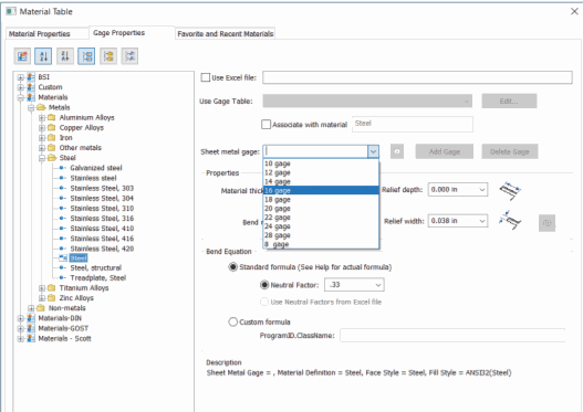
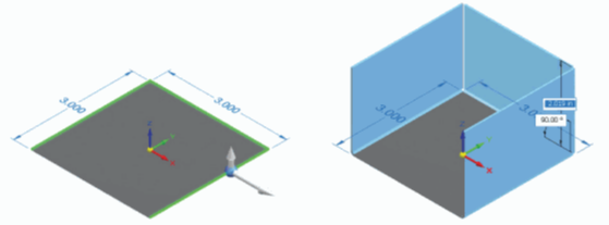
Sheet metal part modeling is much easier when you assign a material and gage (thickness) to your part from the beginning. During design, if you find that your original specified gage is too thick or thin, it can be changed, but defining this setting from the beginning allows you to properly calculate bends. Built-in bend calculations will also correctly calculate bends so that flat patterns have appropriate material added for forming bends.
Depending on your machinery and/or dies, K-factor calculations may not suit your needs. For example, if your dies bend to a sharper radius than the stock material thickness, you need to account for that.
Tip 2: Use built-in sheet metal features whenever possible
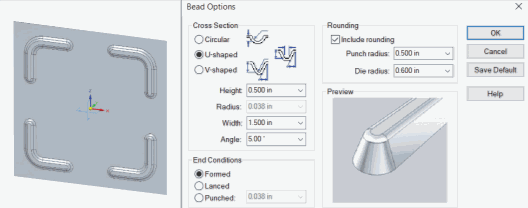
If your design tool supports built-in sheet metal features, take advantage of them. Specialized sheet metal design capabilities such as dimples, gussets, louvers and beads can deliver significant productivity gains compared to general-purpose CAD tools. With a simple sketch and some property parameters, you can take the guesswork out of otherwise complex shapes.
Built-in intelligence can help you save additional time by automatically calculating material treatments and validating parts for manufacturability. In addition, the ability to create manufacturing-ready sheet metal flat patterns helps eliminate scrap and rework.
Tip 3: Use mirror and pattern features to save time and avoid redundancy
Due to the nature of sheet metal applications, it’s common to have features or patterns repeated on your part, whether symmetrical or not. It can be time-consuming to create these features (such as a flange that appears on both sides of a part) one-by-one. But taking a different modeling design approach can be an opportunity to save time.
When you need to create repetitive features instead of modeling each feature multiple times, you can use pattern and mirror commands to quickly replicate what you’ve already done once. With a pattern you can create multiple features, while mirror allows you to create a symmetrical copy of one or more features opposite a selected plane to the opposite side of your part.
If you edit the parent feature of the patterned or mirrored components, it will change all the children of that parent to match that edit.
Tip 4: Use contour flange to reduce your number of features
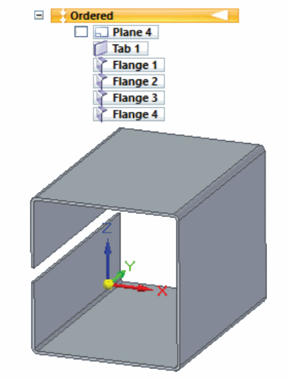
When working in sheet metal, many users create parts by building, or layering tabs and flanges to achieve the desired result. This takes time and clicks and can compromise productivity. It also lengthens the feature tree and creates more parent/child dependencies. Using tab and flange features creates a much longer and complex feature tree. Contour flange achieves the same result in a single feature.
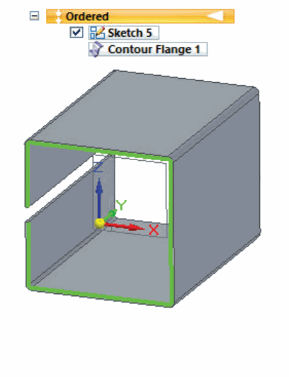
Most shapes that are created using tabs and flanges and multiple features of each can be created more efficiently using contour flange. A contour flange allows you to create tabs and flanges simultaneously, in a single sketch.
Creating parts using contour flanges makes editing those parts easier as well. Edits can be made to a single 2D sketch, instead of on multiple feature sketches to get a desired result.
Tip 5: Verify flat patterns before moving to fabrication
Make sure that what you’re creating in your CAD design is manufacturable by verifying your flat patterns. Don’t assume that because you were able to create a design in your CAD system that the design is therefore manufacturable.
When you validate your design as a flat pattern, you may see interferences where features overlap themselves This means that your sheet metal part as currently designed may fail.
In many cases, minor changes may be required to make the part manufacturable. Failing to recognize these design flaws will result in costly production delays.
Tip 6: Improve your speed and flexibility with synchronous technology
Using traditional modeling methods, sheet metal parts are modeled using standard feature trees and ordered lists of features. But there’s a faster, easier way.
Synchronous technology combines the speed and simplicity of direct modeling with the flexibility and control of parametric design. Unlike history-based CAD, features can be edited independently. You can reorder, reorganize and sort them by name or type. Specialized capabilities allow you to create and make edits to sheet metal features such as dimples and beads, using sketches and engineering parameters, without having to regenerate unrelated geometry or downstream operations.
For example, in order-based modeling, if you need three equal flanges off a tab, you would have to create them using three separate flange features. Using synchronous technology, creating multiple flanges is as simple as clicking on multiple edges and pulling the steering wheel arrow up or down in the direction you want the flanges to go. In one feature, you’ve created all necessary flanges.
Also built into the command is the ability to create a centered flange or offset flange, on the fly. There’s no need to sketch an offset or centered flange.
Synchronous technology can also be used in a “hybrid” method of modeling, in concert with an ordered (historybased) approach. Start your conceptual design with synchronous modeling methods, then switch to ordered for more detailed features.
Tip 7: Don’t make drawings an afterthought
Drawings are often the final deliverable for your design – and in many cases the only representation of your model the shop floor sees. Clear, accurate drawings are essential to communicating your instructions. Make sure your layout is clear, annotations are in place, and bend tables, detail and section views are utilized to provide clarity.
If changes to the model are made after the drawing is created, the drawing should be updated to ensure that the correct information is provided to manufacturing. Likewise, if manual annotations are made on the drawing, make sure that the model is updated to reflect them. This keeps your 3D model as the single source of truth for your design, and makes it easier to re-use or recreate it in the future.
Create flat pattern drawing views. Dimensions can be placed to locate bend lines and bend up/down labels can appear in the bend table and on the flattened view.
Tip 8: Take advantage of 2D nesting
2D nesting is the layout of multiple 2D shapes that we want to cut from a piece of material that provides the most efficient yield (quantity) with as little waste as possible from that piece of material.
In the sheet metal manufacturing industry, nesting is referred to as the process of laying out and cutting flat patterns of many parts from large sheets or plates of metal with as little waste as possible.
2D nesting gives you the ability to reduce tailings, or partial sheets. These tailings and partial sheet usage result in wasted material.
Summary
In theory, manufacturing from sheet metal should be relatively straightforward – you are simply bending flat sheet stock into shapes. But sheet metal parts can be deceivingly complex, and often require substantial time, energy and effort to design and manufacture. By improving your design techniques, you can increase productivity and get your sheet metal designs done accurately, quickly and easily.
Good techniques can help improve performance, but they’re only half of the equation. When you take the potential complexity of sheet metal design into consideration, it becomes obvious that you need a highly specialized set of tools if real productivity and quality gains are to be realized from design through manufacturing.
Solid Edge provides the industry’s best-in-class sheet metal design system, with support for the entire design through-fabrication process. With capabilities to handle complex sheet metal design challenges including manufacturability, Solid Edge streamlines the entire product development process, from sheet metal part design through flat pattern and drawing development.